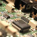
Its using the HC11 and an example multi threaded program with some logic me and my partner came up with. It uses a GM MAP sensor, a Perrin EBC(which is so crappy), and for the boost source we're using a portable tire pressure inflater.
The concept is pretty simple, when the MAPv goes above the voltage we have set on the potentiometer the valve switches over and lets air out, as the pressure falls below the potentiometer set pressure the valve switches over and provides pressure to the MAP sensor.
Its not as quick as some of the ones out there on the market, then again I'd imagine a lot of them use PWM and some sort of PID fuzzy logic controller with a better valve. If I plan on making the switching time any faster, I'll have to move to that.
Also the valve I have is kinda crappy and doesn't respond well to being pulsed, its more of an on off type thing. But I'm still looking into playing with the duty cycle on it. Also there is NO published data on the valve, or which way the air flows... just how you hook it up to your car so we kind of had to deduce stuff from that.
The reason I did this was for a project for school as we had to create a multi threaded environment with semaphores/FIFO queues/ and TCB's. So we weren't really going for functionality, just making it work.
I think I may want to try and get it working with PWM and try and implement a PID controller over the break, but I'm not a big fan of the HC11 :\.
What I do want to try to do is create a little module that will read and store Boost and O2 values so you can read them back and graph them using something like excel and matlab. I'm thinking it wouldn't be too difficult with some flavor of a PIC and a cheap'er LCD.
Pictures and a video will be up tomorrow/Sunday for those of you who care

ps. eat your heart out 3s tech
hehe.